 Schütz,Leistungsschalter,Sensor,Encoder,SPS,Konverter


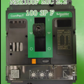
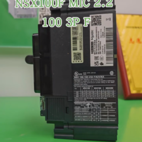
- Modellinterpretation
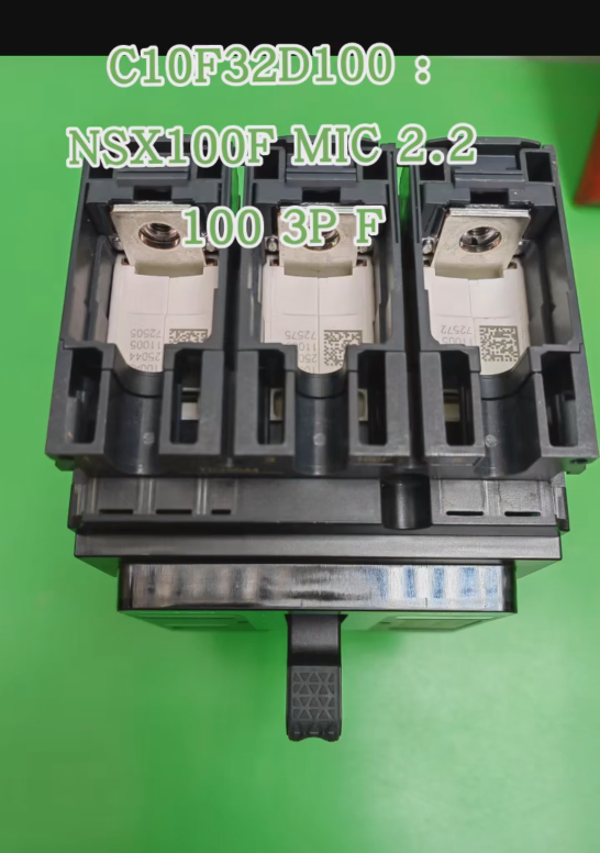
C10F32D100 is the complete order code of Schneider’s new-generation ComPacT NSX series Kompaktleistungsschalter. The meaning of each segment is as follows:
| Codesegment | Bedeutung | Beschreibung |
| C10 | Frame Size and Breaking Capacity | C10 = NSX100F, frame current 100A, breaking capacity Class F (36kA@415VAC) |
| F | Schaltleistungsklasse | F = 36kA@415VAC, suitable for standard industrial applications |
| 3 | Anzahl der Pole | 3 = 3-pole (3P3D, Dreiphasen-Dreileitersystem) |
| 2D | Art der Auslöseeinheit | 2D = MicroLogic 2.2 electronic trip unit with display function |
| 100 | Nennstrom | 100A, adjustable range 90-100A |
- Technische Kernparameter
Grundparameter
| Parameter | Wert | Beschreibung |
| Produkttyp | Kompaktleistungsschalter (MCCB) | New-generation ComPacT NSX100F |
| Nennspannung | 690VAC/50-60Hz | Maximale Betriebsspannung |
| Nennstrom (Iu) | 100A | Dauerbetriebsstrom |
| Ultimative Bruchkapazität (Icu) | 36kA@415VAC | Ultimative Bruchkapazität |
| Betriebsunterbrechungskapazität (ICs) | 36kA@415VAC (100%) | Betriebsunterbrechungskapazität |
| Montageart | Behoben | Standardmontage, Plug-in-Typ optional (C10F32D100P) |
| Protection Category | Kategorie A | Entspricht IEC 60947-2 Standard |
MicroLogic 2.2 Trip Unit Parameters
| Schutzfunktion | Merkmal | Einstellbarer Bereich |
| Long-time Delay Protection (L) | Überlastschutz, inverse time-lag | 0.8-1.0脳Iu (90-100A) |
| Short-time Delay Protection (S) | Kurzschlussschutz, definite time-lag | 3-6脳Iu, einstellbar |
| Instantaneous Protection (ICH) | Short-circuit instantaneous tripping, behoben | 10脳Iu (1000A) |
| Anzeigefunktion | Current measurement and status indication | Real-time display of three-phase current |
Physical and Electrical Characteristics
| Parameter | Wert |
| Stromausfall | 14.1W |
| Gewicht | Approximately 2.5kg |
| Compliance-Standards | IEC 60947-2, GB 14048.2 |
| Zertifizierungen | CE, CCC, RoHS |
III. Funktionsmerkmale
- Umfassender Schutz: Provides three-stage protection including long-time delay, short-time delay and instantaneous protection, effectively preventing overload and short-circuit faults.
- Präzise Kontrolle: Compared with thermal-magnetic trip units (TM series), electronic trip units offer more accurate protection curves and adjustable parameters.
- Statusvisualisierung: MicroLogic 2.2 is equipped with LED display for real-time monitoring of current and fault status.
- Modularer Aufbau: Supports a variety of accessories (Hilfskontakte, Alarmkontakte, Unterspannungsauslöser, usw.) for flexible installation.
- Environmental Friendly: Schneider Green Signature design, reducing energy consumption and carbon footprint.
- Einfache Bedienung: Ergonomic handle for labor-saving operation; front-mounted accessories reduce wiring time by 40%.
- Anwendungsszenarien
- Industrielle Stromverteilungssysteme: Used as main switch or branch switch to protect motors, transformers and distribution lines.
- Elektrische Gebäudesysteme: Low-voltage distribution cabinets in commercial buildings and industrial plants.
- Motorkontrollzentren (MCC): Protect three-phase motors from locked rotor and overload conditions.
- Rechenzentren: Power protection for critical loads to ensure power supply continuity.
- Neuer Energiesektor: DC-side protection of photovoltaic inverters and energy storage systems (additional configuration required).
- Product Comparison
Comparison with Trip Units of the Same Series
| Modell | Art der Auslöseeinheit | Hauptunterschiede | Anwendungsszenarien |
| C10F32D100 | MicroLogic 2.2 | Electronic trip unit with display, three-stage protection | Industrial applications requiring precise protection and monitoring |
| C10F3TM100 | TM100D Thermal-Magnetic Trip | Thermisch-magnetische Auslöseeinheit, two-stage protection, kostengünstig | Simple power distribution without precise adjustment requirements |
| C10F33D100 | MicroLogic 3.2 | Added earth fault protection (30-3000mA) |
Comparison with Chint Alternative Models
| Schneider-Modell | Chint Alternative Model | Ähnlichkeiten | Unterschiede |
| C10F32D100 | NM1-125S/3300 100A | 3-Pole, 100A, 36kA-Ausschaltvermögen | Chint adopts thermal-magnetic trip unit without display; Schneider adopts electronic trip unit with display |
| NM1-125H/3340 100A | 3-Pole, 100A, elektronische Auslöseeinheit | Chint has 50kA breaking capacity with slightly different protection functions |
- Auswahl- und Nutzungsempfehlungen
- Wichtige Auswahlpunkte
Select protection curves according to load types: für Motorlasten, it is recommended to set short-time delay to 5-6×Iu
Breaking capacity should be greater than the expected short-circuit current of the system
Erwägen Sie eine zukünftige Erweiterung; rated current should be slightly higher than the actual load current
- Vorsichtsmaßnahmen bei der Installation
Ensure the mounting surface is flat and the tightening torque meets requirements (screw torque 25N·m)
Corresponding cable lugs must be used for terminal connections to avoid heating caused by poor contact
Leave sufficient heat dissipation space around and avoid close installation with heat-generating components
- Wartungsempfehlungen
Regelmäßige Inspektion (mindestens einmal im Jahr): Aussehen, tightness status, flexibility of operating mechanism
Check contact condition after short-circuit tripping and replace if necessary
Clean with dry compressed air to avoid moisture and dust accumulation
Vii. Leitfaden zur Fehlerbehebung
| Fehlerphänomen | Mögliche Ursachen | Schritte zur Fehlerbehebung |
|---|---|---|
| Failure to Close | 1. Undervoltage release without power supply 2. Fehlfunktion der Auslöseeinheit 3. Mechanical lockout | 1. Steuerspannungsversorgung prüfen (falls ausgestattet) 2. Measure trip unit coil resistance 3. Manually reset the trip mechanism |
| Falsches Auslösen | 1. Überlast 2. Kurzschluss 3. Improper trip unit parameter setting | 1. Laststrom prüfen 2. Check line insulation 3. Reset trip unit parameters |
| No Display After Tripping | 1. Trip unit power supply failure 2. Trip unit damage | 1. Check trip unit power supply 2. Replace the trip unit |







NH42-63-318x560.png "Automatische Transferschalter vom Typ CHINT PC (ATS)NH42-63/4SZ")



