 Contacteur,disjoncteur,capteur,Encodeur,API,Convertisseur

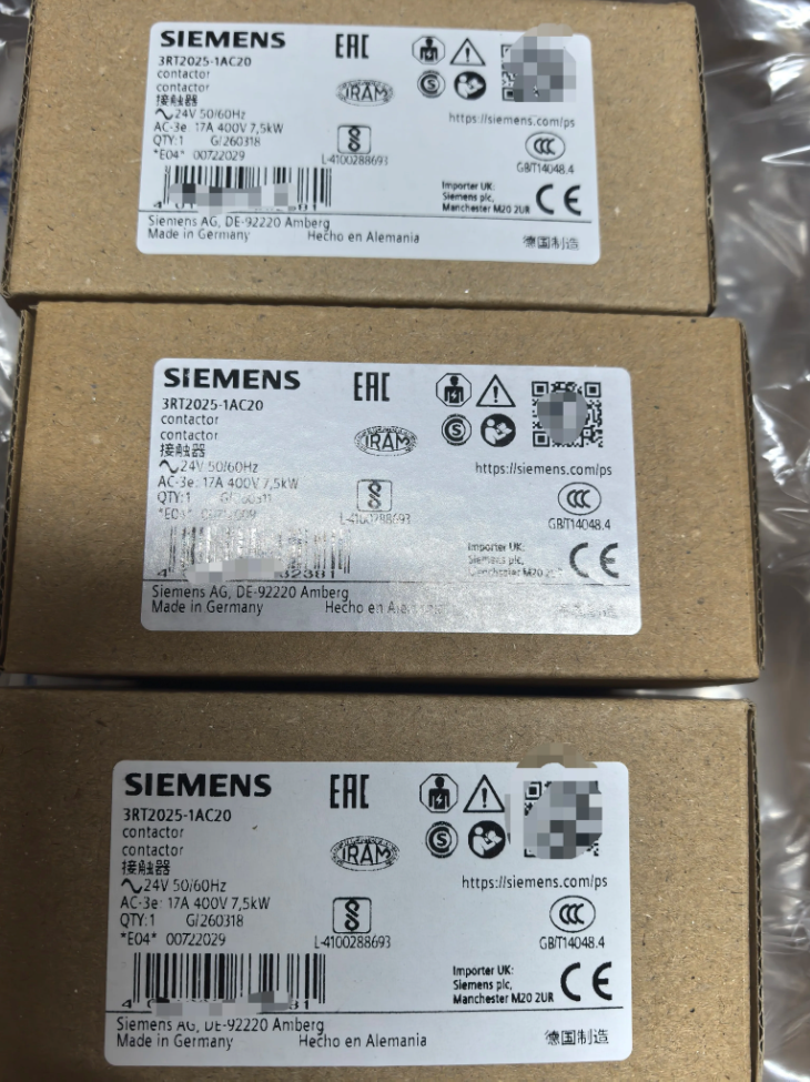

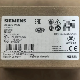
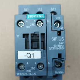
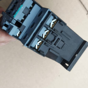
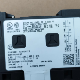
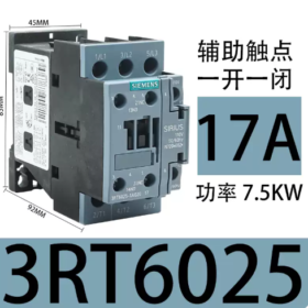
Série de produits: SIRIUS 3RT2 3-pole Power Contactor (Motor Contactor)
Full Order No.: 3RT2025-1AC20
✅ Model Code Explanation
3RT: SIRIUS contactor series
2: New generation SIRIUS Innovations
0: 3-pole motor contactor
25: S0 frame size, AC-3 17A, rated for 7.5kW motor at 400V
1: Built-in 1NO + 1Caroline du Nord contacts auxiliaires
UN: Bobine CA
C: 24V et, 50/60Bobine Hz
20: Screw-type terminal
✅ Core Technical Specifications
| Article | Paramètre |
| Main Contacts Poles | 3P. (3 normally-open main contacts) |
| Courant nominal AC-3 | 17Un @400V |
| Rated Current AC-1 (charge résistive) | 40UN |
| Max.. Tension de fonctionnement | 690V |
| Bobine | 24V et, 50/60Hz |
| Contacts auxiliaires | 1NON + 1Caroline du Nord |
| Taille du cadre | S0 |
| Type de câblage | Bornes à vis |
| Montage | Montage sur rail DIN |
| Classe de protection | IP20 (devant / bornes) |
| Température ambiante de fonctionnement | -25℃ ~ +60℃ |
| Durée de vie mécanique | 10 millions d'opérations |
✅ Typical Applications
Start/stop control of 3-phase asynchronous motors (les fans, pompes, convoyeurs)
CVC, conditionnement, machine tool automation control cabinets
Can be matched with 3RU2 thermal relays for motor overload protection; contacts auxiliaires, surge suppressors and mechanical interlock modules can be added.
✅ Coil Variant Reference for Selection & Remplacement
3RT2025-1AC20: 24V et
3RT2025-1AG20: 110V et
3RT2025-1AN20: 220V et
3RT2025-1AP00: 230V et
3RT2025-1BB40: 24À DC
✅ Replacement Information
- Siemens internal replacement: Old model 3RT1025-1AC20 (abandonné). Direct replacement with 3RT2025-1AC20, mounting dimensions are compatible.
- Référence alternative nationale: Chint NC1-18, Delixi CJX2-1810 (match coil voltage and confirm 1NO+1NC auxiliary contacts).
✅ Troubleshooting Guidelines
- Coil energized but no pull-in: Measure A1/A2 for 24V AC; check burnt coil and loose terminals.
- No output on main circuit after pull-in: Main contacts erosion, inspect L1/L2/L3 and T1/T2/T3.
- Repeated coil burnout: Overvoltage or surge on coil circuit. RC snubber module is recommended for parallel connection.
- Abnormal auxiliary contacts: Auxiliary contacts worn out. External auxiliary contact modules can be fitted.
The built-in 1NO+1NC auxiliary contacts integrated inside 3RT2025-1AC20 cannot be replaced separately.
They are integrated into the contactor housing with no spare parts available. Once the built-in auxiliary contacts are damaged, the whole contactor must be replaced.
Distinguish two concepts:
- Contacts auxiliaires intégrés (1NON+1NC): Integrated inside S0 frame body, non-detachable and non-replaceable individually.
- External add-on auxiliary contact modules (monté à l'avant / monté sur le côté): Detachable and replaceable separately, classified as accessories.
📌 External Auxiliary Contact Module Selection (Détachable & Replaceable)
1) Front-mounted (fit only 1 piece on front face)
3RH2911-1HA11: 1NON+1NC
3RH2911-1HA22: 2NON+2NC
2) Monté sur le côté (can be fitted on left or right side, maximum 2 pièces, one on each side)
3RH2921-1DA11: 1NON+1NC
3RH2921-1DA20: 2NON
3RH2921-1DA02: 2Caroline du Nord
🛠️ Fault Handling Solutions
- Burnt built-in auxiliary contacts: No spare parts available; replace the entire 3RT2025-1AC20 contactor.
- Damaged external auxiliary contact module: Remove the faulty auxiliary contact module and replace it with the same model accessory; reuse the contactor body.
- Insufficient contact quantity: Add front/side mounted auxiliary contact modules listed above.
⚠️ Additional Remarks
For S0 frame (3RT2025), no separate spare main contact kits are available. The whole contactor needs replacement when main contacts are burned. Only S2 and larger frame contactors have independent spare main contacts.
Siemens 3RT2025-1AC20 Main Contacts vs Auxiliary Contacts
- Définition & Fonction
Contacts principaux (L1/L2/L3 ↔ T1/T2/T3)
Fonction: Switch high-power main circuit, directly turn on/off motors and loads
Quantité: 3 normally-open sets (3P.)
Notation: AC-3 17A@400V for 7.5kW motor; AC-1 40A for resistive load
Circuit: High-power main circuit
Structure: Oversized thick silver-alloy contacts with arc extinguishing chamber to withstand breaking arc under high current
Remarque: Cadre S0, main contacts cannot be replaced individually. Full contactor replacement required after damage.
Contacts auxiliaires (Built-in 1NO+1NC, expandable with 3RH accessories)
Fonction: Retour de signal, verrouillage, verrouillage (control circuit logic, not for high-power load driving)
Quantité: Built-in 1NO +1NC. Expandable by external modules
Notation: Faible courant, typically ≤6A for PLC input, relay coils and indicator lamps
Circuit: Low-power control circuit
Structure: Small silver contacts without heavy-duty arc extinguishing, only for small current breaking
Remarque: Built-in auxiliary contacts are integrated and non-replaceable; external 3RH auxiliary modules can be assembled and replaced individually.
- Tableau de comparaison
| Article de comparaison | Contacts principaux | Contacts auxiliaires intégrés |
| Marquage des bornes | L1/L2/L3, T1/T2/T3 | 13/14 (NON normalement ouvert), 21/22 (NC normalement fermé) |
| Capacité de charge | High current for motors and heaters | Low current only for signal, interlock and latching |
| Courant nominal | AC-3:17Un @400V | Typically 6A (AC-15) |
| Extinction d'arc | With arc chute for heavy arc | No heavy-duty arc suppression, only for minor arc |
| Individually Replaceable | ❌ Not available (Cadre S0) | ❌ Built-in non-replaceable; ✅ External auxiliary modules replaceable |
| Utilisation typique | Main power supply switching for motors | Contactor latching, running feedback, verrouillage, voyant lumineux, PLC acquisition |
- Exemple de câblage typique
- Contacts principaux: 3-phase power supply feeds L1/L2/L3 on contactor top terminals; bottom terminals T1/T2/T3 connect to motor.
- Contacts auxiliaires
13-14 (NON normalement ouvert): Latching circuit or send “contactor energized” feedback signal to PLC.
21-22 (NC normalement fermé): Verrouillage électrique (forward/reverse circuit, prevent simultaneous pull-in of two contactors causing 3-phase short circuit).
- Fault Differentiation
Main Contacts Failure: Motor weak rotation, perte de phase, overheating or arcing at terminals, load cannot power up normally.
Auxiliary Contacts Failure: Motor can start/stop normally, but latching fails, loss of feedback signal, interlock invalid. Main power circuit remains unaffected.
- Avertissement important
Never use auxiliary contacts to switch motors, heaters or other high-power loads. Contact erosion will occur rapidly. High-power loads must be wired via main contacts.
Siemens 3RT2025-1AC20|Application Scenarios of Main Contacts and Auxiliary Contacts
- Contacts principaux (L1/L2/L3 ↔ T1/T2/T3, 3 sets of high-power normally-open contacts)
Core purpose: Switch high-power main circuit and carry load operating current
✅ Applicable scenarios:
- Direct start-stop of 3-phase motors (le plus courant): Pompes, les fans, convoyeurs, compresseurs d'air, machine tool spindle motors. This model is rated for 7.5kW 400V 3-phase motors.
- 3-phase resistive load control: 3-phase heating elements, large 3-phase dehumidification heaters, max 40A under AC-1 rating.
- High-power switching in power distribution circuits: Power switching for heavy loads inside control cabinets.
❌ Ne convient pas aux:
Signaux API, voyants lumineux, small relay coils and other low-current control circuits;
Logical interlock or status feedback.
Caractéristiques: Equipped with arc extinguishing chamber and thick silver contacts, withstand motor inrush current and breaking arc.
- Contacts auxiliaires (Built-in 1NO+1NC, bornes:13-14 NON,21-22 Caroline du Nord; expandable with 3RH external modules)
Core purpose: Low-current signal in control circuit, only transmit logic status, no high-power load driving
✅ Normally Open NO (13-14) Scénarios typiques
- Contactor latching (self-holding): Maintain coil energized after releasing start pushbutton to keep motor running continuously.
- Running status feedback: Send signal to PLC, DIO module or indicator lamp for HMI to display “contactor pulled in, equipment running”.
- Sequential startup: Use NO contact to trigger coil of next relay/contactor after this contactor pulls in, to realize sequential start-up.
✅ Normally Closed NC (21-22) Scénarios typiques
- Verrouillage électrique (classic application): Connected in series to coil circuit of reverse contactor in forward/reverse control circuit, to avoid 3-phase short circuit caused by simultaneous pull-in of forward and reverse contactors.
- Faute / stop feedback: NC closed when contactor is open, used for stop status acquisition.
- Safety circuit interlock: NC contact conducts when contactor is de-energized, serving as ready signal.
Auxiliary contacts are low rated (AC-15 approx.6A), only for low-current control circuits. Do NOT use auxiliary contacts to directly control motors or high-power heating loads.
Quick Selection Rule
Moteurs, high-power heaters, 3-phase power → Main Contacts
Verrouillage, verrouillage, PLC signal, running indicator lamp, logic linkage → Auxiliary Contacts
On-site Quick Fault Diagnosis
Le moteur ne fonctionne pas, perte de phase, hot or arcing terminals → Most likely main contact fault
Motor can start and stop, but stops immediately once start button released, no running feedback, risk of short circuit due to failed interlock → Most likely auxiliary contact fault





NH42-63-318x560.png "Commutateurs de transfert automatiques de type PC CHINT (ATS)NH42-63/4SZ")



