 Schütz,Leistungsschalter,Sensor,Encoder,SPS,Konverter


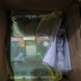
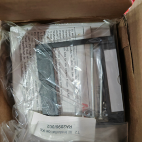
Technical Specifications and Application Guide for ABB MCCB 1SDA050999R1
- Modellerklärung
| Modellteil | Beschreibung |
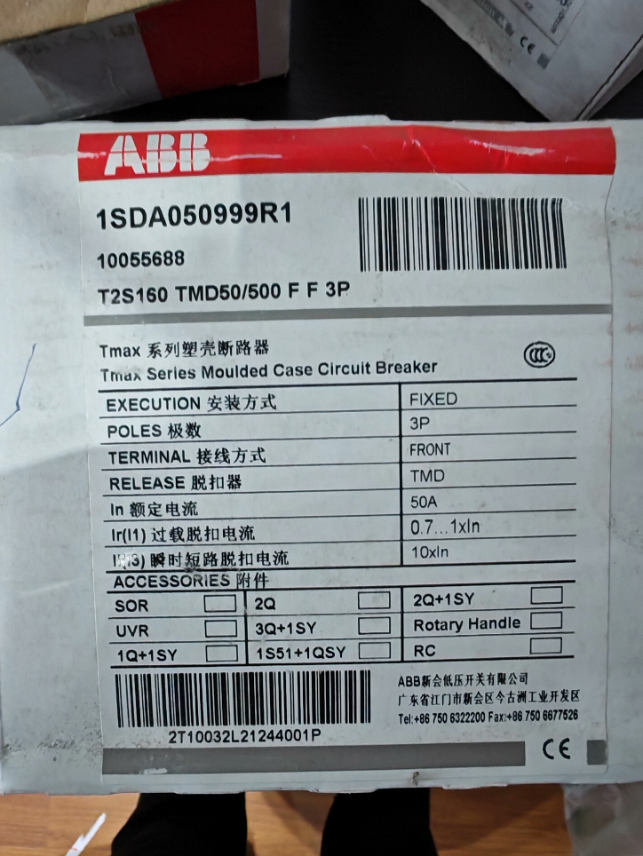
| 1SDA050999R1 | Unique global product code for ABB SACE Tmax T series Kompaktleistungsschalter |
| T2S | Produktserie: Tmax T2 series; S stands for standard breaking capacity (50Die) |
| 160 | Rahmennennstrom: 160A |
| TMD | Art der Auslöseeinheit: Thermisch-magnetische Auslöseeinheit, D-Kurve (motor protection type) |
| 50-500 | Trip unit rated current range: 50A (bewertet), 500A (instantaneous trip value) |
| 3P | Anzahl der Pole: 3 Stangen |
| F F | Montage: Behoben; Verbindung: Frontanschluss |
- Schlüsselparameter
Elektrische Parameter
| Artikel | Wert |
| Nennbetriebsspannung (Und) | 400V und (50/60Hz), 690V AC optional |
| Bemessungsisolationsspannung (Ui) | 690V und |
| Bemessungsstoßspannungsfestigkeit (Ump) | 8kV |
| Nennstrom (In) | 50A (adjustable range 50–500A) |
| Rahmennennstrom (Icu) | 160A |
| Bruchkapazität | 50Die (415V und), 36Die (690V und) |
| Kurzzeitiger Stromwiderstand (Icw) | 16Die (1S) |
| Reisekurve | Typ D, konform mit IEC 60947-2 |
| Thermal trip range | 50–500A (einstellbar) |
| Magnetic trip range | 5–10 Zoll (einstellbar) |
| Nennfrequenz | 50/60Hz-kompatibel |
Mechanische Parameter
| Artikel | Wert |
| Betriebsmodus | Handbuch (Standard), motor operation optional |
| Mechanische Ausdauer | 10,000 Operationen (at rated) |
| Elektrische Ausdauer | 1,000 Operationen (rated short-circuit breaking) |
| Schutzart | IP30 (konform mit IEC 60529) |
| Terminals | Frontanschluss, suitable for cable cross-section: 16–70mm² |
| Montage | Behoben, Standard-35-mm-DIN-Schienenmontage |
- Montagemaße
| Artikel | Wert (mm) |
| Breite | 90 |
| Höhe | 150 |
| Tiefe | 105 |
| Abstand der Befestigungslöcher | Standardmäßige 35-mm-DIN-Schiene |
| Klemmenabstand | Entspricht den IEC-Standards, suitable for standard cable connections |
- Anwendungshinweise
4.1 Auswahlrichtlinien
Suitable for motor protection and general industrial power distribution systems, especially where D-curve tripping is required
Derate when ambient temperature exceeds 40°C: 1% per °C rise; max operating temperature 60°C
Derate at altitudes above 2000m: 1% per 100m rise; max altitude 4000m
Select appropriate trip setting current according to actual load, ensuring I_load ≤ In ≤ I_cable
4.2 Installationsanforderungen
Ensure breaker is OFF and voltage-free with multimeter before installation
Mount on 35mm standard DIN rail, ensure firm fixing to avoid vibration effects
Tighten terminals with suitable torque (recommended 6N·m) to prevent overheating from poor contact
Keep sufficient heat dissipation space: at least 50mm clearance around the breaker
Avoid installation in damp, staubig, corrosive gas or heavy vibration environments
4.3 Betrieb und Wartung
Inspect mechanical operating mechanism regularly (annually recommended) to ensure smooth ON/OFF
Test tripping function regularly (semi-annually recommended) to ensure reliable protection
Clean surface with dry soft cloth; avoid chemical cleaners
Record operation count; replace before reaching mechanical endurance
After short-circuit interruption, check breaker condition and replace if necessary
- Fehlerbehebung
| Fehlersymptom | Mögliche Ursachen | Lösungen |
| Fails to close | 1. Undervoltage trip not powered | 1. Steuerspannungsversorgung prüfen |
| 2. Mechanische Blockierung | 2. Operate manually several times to clear jam | |
| 3. Fehler der Auslöseeinheit | 3. Replace trip unit module | |
| Häufiges Stolpern | 1. Überlast | 1. Laststrom prüfen |
| 2. Kurzschluss | 2. Troubleshoot short circuit | |
| 3. Improper trip setting | 3. Reset trip settings | |
| 4. Loose connection causing heating | 4. Check and tighten terminals | |
| Kontaktablation | 1. Langfristige Überlastung | 1. Replace with higher-rated breaker |
| 2. Insufficient breaking capacity | 2. Upgrade to higher breaking capacity model | |
| 3. Excessive operating frequency | 3. Reduce operation frequency or replace suitable model | |
| Trip unit does not operate | 1. Trip unit damaged | 1. Auslöser ersetzen |
| 2. Falsche Verkabelung | 2. Check wiring correctness | |
| 3. Excessively low ambient temperature | 3. Improve ambient temperature or select low-temperature model | |
| Motor operation mechanism fails | 1. Control voltage below 85% Und | 1. Steuerspannungsversorgung prüfen |
| 2. Limit switch not reset | 2. Manually reset limit switch | |
| 3. Motor fault | 3. Replace operating mechanism motor |
- Brand Replacement Solutions
6.1 ABB Alternative Models
Upgrade-Modell: XT2S 160 TMA 50–500 3p F F (1SDA067555R1), Tmax XT series, höhere Leistung, compatible mounting dimensions
Wirtschaftliche Alternative: Formula A1B 125 TMF 50–500 3p F F (1SDA066702R1), geringere Kosten, same basic protection functions
6.2 Competitive Brand Equivalents
| Marke | Ersatzmodell | Hauptunterschiede |
| Schneider | CVS160F TMD50 3P 50kA | Same breaking capacity, slight dimension difference, consistent trip curve |
| Siemens | 3VL160 50A 3P TMD | Same frame current, 50kA-Ausschaltvermögen, different operating mechanism design |
| Chint | NM1-160S/3300 50A | Inländische Alternative, kostengünstig, basic functions consistent |
| Lecker | CDM1-160S/3300 50A | Inländische Alternative, hohes Preis-Leistungs-Verhältnis, compliant with IEC standards |
Detailed Mounting Dimensions for ABB MCCB 1SDA050999R1
- Basic Model and Mounting Type Confirmation
Vollständiges Modell: ABB SACE Tmax T2S 160 TMD50–500 3p F F (1SDA050999R1)
Montageart: Behoben (F), Frontanschluss (F)
Polen: 3 Stangen (3P)
Serie: Tmax T series (not XT upgraded series)
- Core Mounting Dimensions (Einheit: mm)
| Artikel | Wert | Bemerkungen |
| Breite (W) | 90 | Standard 3-pole width, DIN rail compatible |
| Höhe (H) | 130 | Including operating handle, fixed standard height |
| Tiefe (D) | 70 | Standard depth for fixed front connection, excluding terminal extension |
| Montage | Standardmäßige 35-mm-DIN-Schiene | Konform mit IEC 60715, snap-in mounting |
| Abstand der Befestigungslöcher | Für 35-mm-DIN-Schiene | Rail thickness 1.0–1.5mm compatible |
| Klemmenabstand | Phase spacing 25mm, N-line spacing 25mm | Standard wiring, suitable for 16–70mm² cable |
| Terminal height | 45mm | From rail plane to top of terminals |
| Handle height | 130mm | From rail plane to top of handle |
| Nettogewicht | 1.12kg | Without packaging |
- Detailed Dimension Diagram Description
3.1 Front View Dimensions
Total width: 90mm (3-Pole)
Total height: 130mm (including handle)
Handle travel: ca. 25mm (ON–OFF difference)
Trip indicator window: 30mm from top, centered
3.2 Side View Dimensions
Total depth: 70mm (fixed front connection)
DIN rail slot: 15mm from bottom, 35mm breit
Terminal connection depth: ca. 15mm from front surface
Anzugsdrehmoment der Klemmen: 6N·m (for M6 bolts)
3.3 Installation Clearance Requirements
| Standort | Min. Distanz | Beschreibung |
| Left and right | 50mm | For wiring and heat dissipation |
| Top and bottom | 50mm | Prevent heat buildup, ensure operating space |
| Front operating space | 100mm | For handle operation and maintenance |
| Hinteren (in cabinet) | 30mm | For cable bending radius |
- Installationskompatibilität
4.1 DIN Rail Compatibility
Kompatibel mit standardmäßiger 35-mm-DIN-Schiene (IN 60715:2001)
Rail material: steel or aluminum, recommended thickness 1.2mm
Mounting clips: self-contained spring clips, no extra fixings needed
4.2 Dimension Comparison with XT Series
| Artikel | Tmax T2S 160 (1SDA050999R1) | Tmax XT2S 160 | Unterschied |
| Breite | 90mm | 90mm | Dasselbe, interchangeable position |
| Höhe | 130mm | 130mm | Dasselbe, panel cutout universal |
| Tiefe | 70mm | 82.5mm | XT series deeper; check cabinet space before replacement |
| Montage | Dasselbe (35mm DIN-Schiene) | Dasselbe | Vollständig kompatibel |
4.3 Verkabelungskompatibilität
Suitable cable cross-section: 16–70mm² (Kupfer), crimped lugs recommended
Terminaltyp: plate terminals with lock washers
Connection direction: Frontanschluss, vertical or horizontal incoming
- Installationshinweise
- Confirm breaker is OFF and voltage-free before installation
- Ensure snap-in is fully engaged on DIN rail
- Tighten terminals with 6N·m torque to avoid heating
- Keep at least 50mm clearance between adjacent breakers
- Umgebungstemperatur: -5°C bis +40°C; derate above 40°C
- Technical Dimensions
Produktcode: 1SDA050999R1
Montageart: Behoben, Frontanschluss
Polen: 3P
Breite: 90 mm
Höhe: 130 mm
Tiefe: 70 mm
Montageschiene: 35 mm DIN-Schiene (IN 60715)
Klemmendrehmoment: 6 N·m
Nettogewicht: 1.12 kg







NH42-63-318x560.png "Automatische Transferschalter vom Typ CHINT PC (ATS)NH42-63/4SZ")



