 Contacteur,disjoncteur,capteur,Encodeur,API,Convertisseur

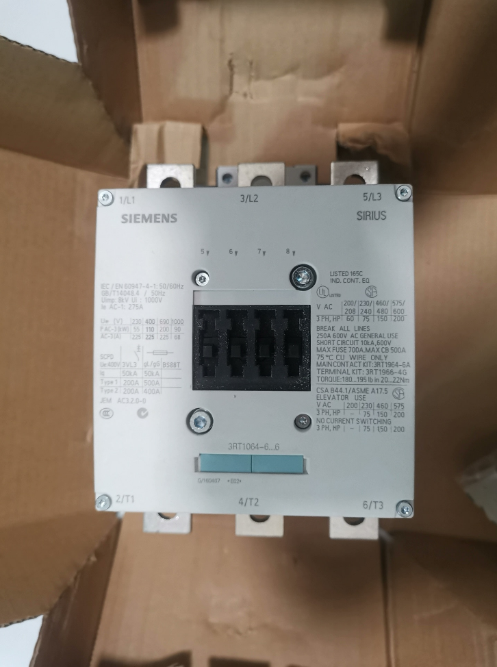

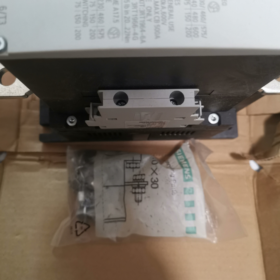
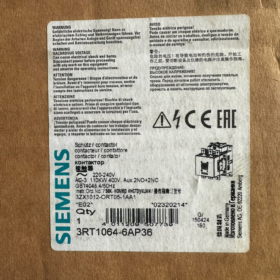
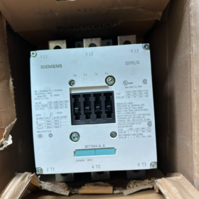
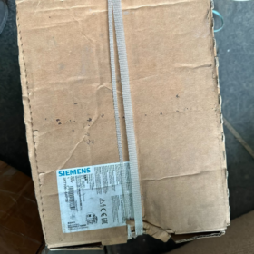
3RT1064-6AP36
- 3RT: SIRIUS Contacteur électromagnétique Série
- 1: Série SIRIUS 3RT1 importée classique (Equivalent national: 3RT5/3RT6)
- 0: 3-contacteur polaire pour charges moteur (3AUCUN contact principal)
- 64: Taille de cadre S10, Courant nominal AC-3 225 UN
- 6: Mécanisme de commande électromagnétique conventionnel (bobine non électronique)
- UN: Code de tension de bobine → AC/DC 220 ~ 240 V (Bobine universelle AC/DC)
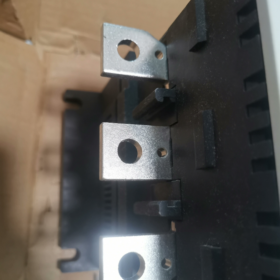
- P.: Connexion du jeu de barres du circuit principal
- 36: Contacts auxiliaires intégrés en permanence 2NO + 2Caroline du Nord
Description complète: 3-contacteur de puissance de pôle, Cadre S10, bornes de jeu de barres, 220Bobine ~240 V CA/CC, fixé 2 Normalement ouvert + 2 Contacts auxiliaires normalement fermés.
- Principales spécifications électriques
| Article | Paramètre |
| Configuration des contacts principaux | 3P Normalement ouvert (3NON) |
| Courant de fonctionnement nominal AC-3 / AC-3e à 400 V | 225 UN |
| Puissance nominale du moteur (3-phase, 400 V) | 110 kW |
| Courant de fonctionnement nominal AC-4 à 400 V | 195 UN |
| Tension de la bobine de commande | UC = 220~240 V CA/CC (Climatisation universelle & CC) |
| Plage de fonctionnement de la bobine | 0.7~1,25 × tension nominale |
| Contacts auxiliaires standards | 2NON + 2Caroline du Nord (Intégré, non amovible) |
| Taille du cadre | S10 |
| Connexion du circuit principal | Connexion par jeu de barres (fixation par boulon) |
| Auxiliaire & connexion de la bobine | Bornes à vis |
| Tension d'isolement nominale | 1000 V |
| Degré de pollution | 3 |
Capacité de connexion du câble
Circuit principal: Câble toronné 70~240 mm²
Circuit auxiliaire: 0.5~4 mm²
- Contour & Informations d'installation
Méthode de montage: Montage par vis sur plaque de base (Montage sur rail DIN NON pris en charge; le grand cadre S10 ne peut être fixé que sur la plaque de base de l'armoire)
Classe de protection avant: IP00
Température ambiante de fonctionnement: -25℃ ~ +60℃ (fonctionnement à pleine charge à 60 ℃)
- Scénarios d'application typiques
Démarrage direct des moteurs asynchrones triphasés, contacteur principal pour démarreurs étoile-triangle, Contournement du VFD
Compresseurs d'air, pompes à eau, les fans, machines de moulage par injection, entraînements de ligne de production haute puissance
CVC, centrale électrique, métallurgie, circuits électriques de grue portuaire
⚠️ Non recommandé pour les opérations lentes à long terme sous service AC-4; sélectionnez une taille de cadre plus élevée pour les applications start-stop fréquentes.
- Référence de sélection alternative
1) Remplacement direct du fabricant d'origine (Siemens d'origine)
3RT1064-6AP36 (Modèle de sujet, 220Bobine ~240 V CA/CC)
Variantes de tension de bobine:
3RT1064-6AP36 = 220~240 V CA/CC
3RT1064-6BP36 = 110~127 V CA/CC
2) Alternative améliorée
3RT1065-6AP36: Cadre S10, AC-3 265 UN (Capacité supérieure, dimensions de montage identiques)
⚠️ Distinction importante: 3La série RT12xx est constituée de contacteurs sous vide de construction différente; pas directement interchangeable.
Modèle économique domestique: 3RT5064 (Bobine AC uniquement, structure terminale différente; ne peut pas remplacer directement le type de jeu de barres importé 3RT1064).
- Rappels des pièges de sélection
- Le circuit principal adopte une connexion par jeu de barres, pas de bornes de câble; des accessoires d'adaptateur de borne sont requis si un câblage est nécessaire.
- Cadre S10 sans embase rail DIN, seul le montage sur plaque de base est disponible.
- Bobine universelle AC/DC; compatible avec les circuits de commande AC230 V et DC220 V.
- Les contacts auxiliaires 2NO+2NC sont intégrés en permanence, ne peut pas être supprimé ou reconfiguré librement.
- Désignation de commande standard avec trait d'union: 3RT1064-6AP36, n'omettez pas le trait d'union.
- Accessoires compatibles en option
3Relais de surcharge thermique RU (Classement du cadre S10)
Suppresseur de surtension (Réseau RC, varistor pour la protection des bobines)
Kits de verrouillage mécanique (pour paires de contacteurs avant/arrière)
Adaptateurs de bornes de circuit principal (transition câble-jeu de barres)
Dimensions de montage – Siemens 3RT1064-6AP36 (Cadre S10)
Condition préalable importante: Le montage sur rail DIN n'est pas pris en charge; uniquement montage par boulon sur la plaque de base
- Dimensions extérieures hors tout (L × H × P, mm)
Largeur W: 145 mm
Hauteur H: 210 mm
Profondeur D: 202 mm (occupation de la profondeur interne de l'armoire)
- Dimensions du trou de montage de la plaque de base (Critique pour le traitement de la tôle des armoires)
4 fixation à travers des trous, spécification du boulon: M8
- Entraxe horizontal (gauche-droite): 124 mm
- Entraxe vertical (haut-bas): 186 mm
- Diamètre du trou de montage: Φ9 mm (pour boulons M8)
Contour des centres des trous de montage: 124 mm (W) × 186 mm (H)
- Dégagement de câblage pour la barre omnibus du circuit principal
Bornes principales exposées en haut et en bas pour l'installation du jeu de barres:
Espacement des phases: 50 mm
Boulon de borne: M12
Épaisseur maximale recommandée du jeu de barres ≤12 mm
- Dégagement minimum pour l'installation de l'armoire (Spécification officielle de dissipation thermique de Siemens)
Dégagement supérieur au-dessus du contacteur: ≥10 mm
Dégagement inférieur sous le contacteur: ≥10 mm
Gauche & dégagement du côté droit: ≥10 mm
Dégagement avant (vers le bouclier d'arc): ≥20 millimètres
Un jeu insuffisant entraîne une augmentation de la température et un fonctionnement déclassé.
- Poids
Poids net de l'unité: environ. 7.8 kilos
- Notes d'installation supplémentaires
- 3RT1064-6AP36 = version connexion par jeu de barres. Les modèles terminés par câble du même châssis partagent des dimensions globales identiques, seule la structure du terminal diffère.
- 3RT1065 (265 UN) de la même série utilise le cadre S10; les dimensions de montage sont entièrement interchangeables, la disposition des trous de la plaque de base peut être réutilisée.
- Distance minimale centre à centre entre deux contacteurs côte à côte avec verrouillage mécanique pour circuit marche avant/arrière: 150 mm.
- Pour un fonctionnement continu à pleine charge au-dessus d'une température ambiante de 40 ℃, étendre le dégagement de dissipation thermique environnant au minimum 15 mm.
Paramètres de durée de vie – Siemens 3RT1064-6AP36 (Cadre S10)
- Durée de vie mécanique (Valeur typique de la fiche technique officielle)
Endurance mécanique: 10,000,000 cycles de fonctionnement (10 millions de fois)
Définition: Cycles d'ouverture/fermeture à vide sans charge du circuit principal. Contacts auxiliaires mécaniques standards intégrés (2NON+2NC) ne réduit pas la durée de vie mécanique.
⚠️ Distinction:
Si des modules auxiliaires électroniques sont installés → endurance mécanique réduite à 5,000,000 cycles.
Les contacts auxiliaires mécaniques 2NO+2NC intégrés standard de ce modèle ne sont pas soumis à cette limitation.
- Durée de vie électrique (Contacts principaux, référence clé pour la sélection)
Conditions de service: AC-3, 400 V, démarrage-arrêt normal du moteur (coupure du courant de démarrage 6×Ie)
Endurance électrique ≈ 200,000 cycles (200,000 fois)
Service progressif AC-4 (rotor bloqué, marche arrière fréquente): La durée de vie électrique diminue considérablement, généralement limité à des dizaines de milliers de cycles. Sélectionnez un contacteur de puissance supérieure ou un contacteur AC-4 dédié pour les applications de jogging fréquentes.
- Notes complémentaires clés
- Durée de vie mécanique ≠ Durée de vie électrique
L'endurance mécanique reflète la durabilité du noyau magnétique, ressorts et mécanisme de transmission; l'endurance électrique est limitée par l'érosion de l'arc de contact. Dans la plupart des conditions de fonctionnement, la durée de vie électrique expire en premier.
- Influences environnementales
Haute température, poussière, humidité, L'écart de tension de la bobine et les vibrations réduiront la durée de vie mécanique et électrique..
- Fréquence de fonctionnement maximale autorisée
Service standard: ≤1200 cycles/heure. Le dépassement de cette fréquence nécessite un déclassement du courant, entraînant une élévation de température aggravée et une réduction accélérée de la durée de vie.
- Interchangeabilité dans le cadre
Tous les contacteurs de châssis S10, y compris 3RT1064 / 3RT1065 partage une endurance mécanique uniforme de 10 millions de cycles, applicable pour référence.







NH42-63-318x560.png "Commutateurs de transfert automatiques de type PC CHINT (ATS)NH42-63/4SZ")



