 Contacteur,disjoncteur,capteur,Encodeur,API,Convertisseur

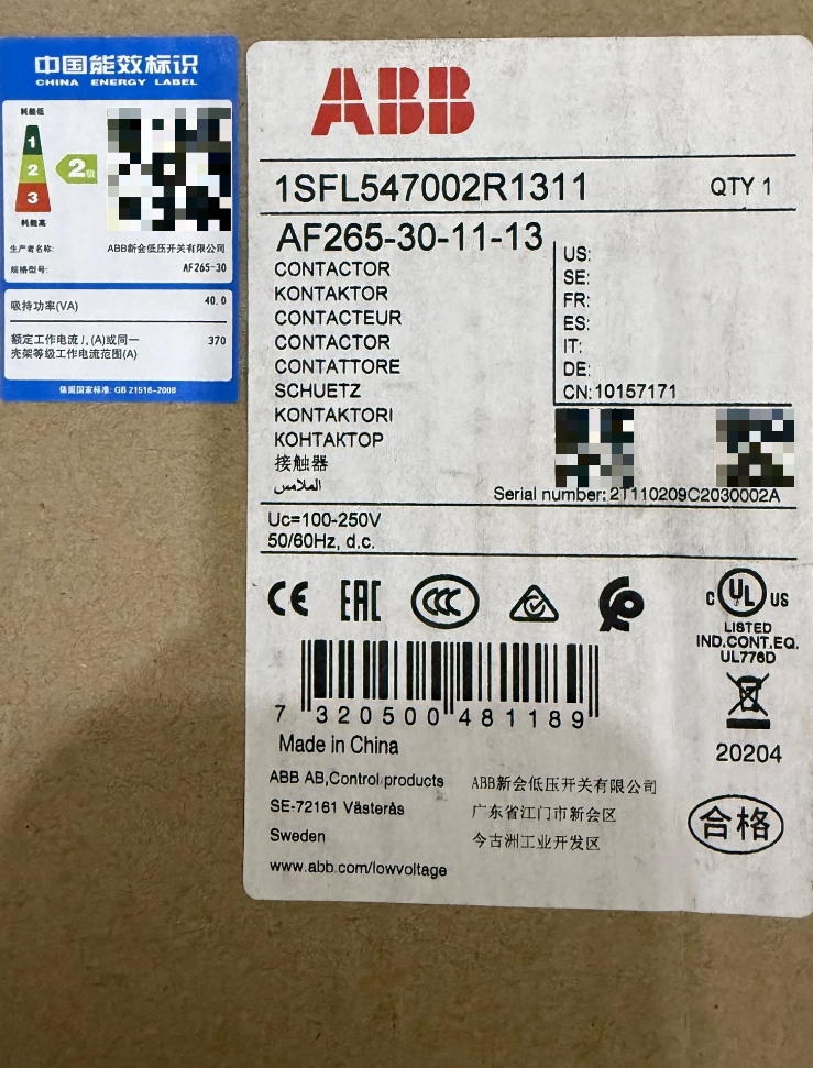

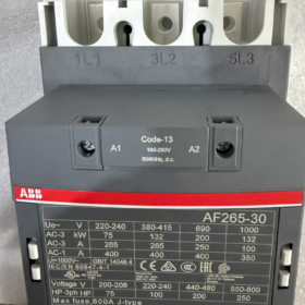
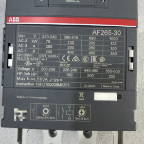
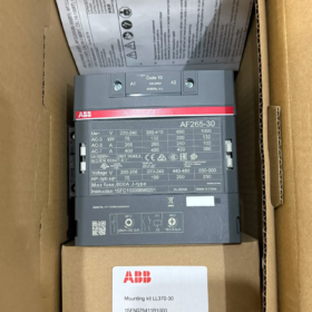
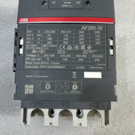
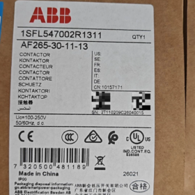
Numéro de commande: 1SFL547002R1311;Numéro de matériau.: 10157171
Série: Série AF 3-Contacteur de pôle avec bobine électronique universelle AC/DC
- Décodage du code modèle
| Segment de modèle | Description |
| DE | Série AF, Bobine électronique universelle AC/DC à large plage, suppression de surtension intégrée; aucun réseau RC externe ou varistance requis |
| 265 | Courant de fonctionnement nominal 265 A sous AC‑3 à 400 V; Courant thermique conventionnel (AC‑1): 400UN |
| 30 | 3-pôle, tous les contacts principaux normalement ouverts (NON); pas de principal normalement fermé (Caroline du Nord) contacts |
| 11 | Contacts auxiliaires intégrés: 1NON +1NC |
| -13 | Code bobine: 100-250 V CA/CC (50/60 Hz + Compatible CC) |
✅Caractéristiques principales: La bobine unique prend en charge AC 100-250V & C.C 100-250 V; haute tolérance aux fluctuations de tension; faible consommation d'énergie de maintien; fonctionnement silencieux.
- Spécifications électriques de base
| Article | Valeur |
| Nombre de pôles principaux | 3P. (3 contacts principaux NON) |
| Courant moteur AC‑3 (400 V) | 265 UN; Puissance moteur 132 kW |
| Charge résistive AC‑1 | 400 UN |
| Tension assignée d'isolement Ui | 1000 V(CEI) /600 V(UL) |
| Tension assignée de tenue aux chocs Uimp | 8 kV |
| Tension de commande de bobine | 100‑250 V CA/CC 50/60 Hz‑CC |
| Contacts auxiliaires | 1NON+1NC (monté à l'avant, non amovible) |
| Endurance mécanique | 5 millions de cycles de manœuvres |
| Fréquence de fonctionnement maximale | 300 opérations/heure |
| Tension d'appel | 80 % de la tension nominale de la bobine inférieure; Tension de chute 55 % de la tension nominale de la bobine inférieure |
III. Environnemental & Paramètres mécaniques
| Article | Valeur |
| Température ambiante de fonctionnement (sans relais thermique) | -40 ℃ ~ +70 ℃; -25 ℃ ~ +55 ℃ avec relais de surcharge thermique |
| Température de stockage | -40 ℃ ~ +70 ℃ |
| Altitude sans déclassement | ≤3000m; déclassement requis au-dessus de 3000m |
| Dimensions hors tout (L×H×P) | 140 mm × 225 mm × 180 mm |
| Poids net | 3.9 kilos |
| Type de borne | Circuit principal: jeu de barres / bornes à boulon; Circuit de commande: bornes à vis |
| Méthode de montage | Montage sur rail DIN vertical ou à vis sur plaque arrière, montage latéral ou inversé strictement interdit |
Certifications: CCC, CE, UKCA, CAE, Certification marine DNV; Sécurité fonctionnelle: SIL2, ISO13849-1 Cat.B.
- Principe de fonctionnement approfondi
Les contacteurs de la série AF adoptent une bobine de type redresseur électronique, différent des contacteurs AC traditionnels:
- Appliquer 100-250 V AC ou DC à A1/A2; le circuit électronique interne redresse l'entrée en courant continu pour piloter la bobine électromagnétique.
- Puissance instantanée élevée pour le pull-in, puis passez à une faible puissance de maintien CC; Chauffage du serpentin beaucoup plus faible que les serpentins AC conventionnels.
- L'absorbeur de surtension TVS intégré dissipe la force électromagnétique inverse lors de la mise hors tension de la bobine. Ne connectez PAS de réseaux RC externes ou de varistances en parallèle; les appareils externes peuvent provoquer un dysfonctionnement ou des dommages permanents.
- L'armature magnétisée CC élimine le bourdonnement CA de 50 Hz.
Définition du terminal
Côté ligne du circuit principal: 1L1, 3L2, 5L3; côté charge: 2T1, 4T2, 6T3
Bobine: A1, A2 (non polaire pour AC & CC)
Contacts auxiliaires: 13-14 (NON); 21-22 (Caroline du Nord)
- Liste de colisage standard & Accessoires en option
Livraison standard
- AF265-30-11-13 Unité de contacteur ×1
- Manuel du produit, certificat de conformité
❗Non inclus: Relais de surcharge thermique, verrouillage mécanique, blocs complémentaires auxiliaires, bouclier de sécurité des bornes.
Accessoires commandés séparément
| Accessoire | Fonction |
| TA275 VOUS | Relais de surcharge thermique correspondant (80-275A) |
| CAL19‑11 | Bloc de contacts auxiliaires à montage latéral (1NON+1NC) |
| VM265 | Verrouillage mécanique (pour l'inversion du service) |
| AF‑MTP | Capot de protection des bornes du circuit principal |
- Compatibilité entre marques & Référence de remplacement
⚠️Vérifiez la valeur nominale de la bobine 100-250VAC/DC et AC-3 265A avant le remplacement..
| Modèle original | Équivalent à ajustement direct | Remarques |
| ABB AF265‑30‑11‑13 | A265‑30‑11 (Héritage EH265) | Les anciennes bobines de la série EH sont uniquement CA / CC uniquement; les bobines ne peuvent pas être échangées directement |
| Équivalents concurrents | Siemens3RT1066‑6AP36; SchneiderLC1D245M7 | Pas de bobine AC/DC native à large plage de 100 à 250 V pour Siemens/Schneider; sélectionner la bonne variante de bobine |
VII. Scénarios d'application typiques
- Ventilateur & démarrage du moteur de grande taille de la pompe (CVC, climatisation centrale, traitement de l'eau)
- Compresseur d'air, commande du moteur de l'extrudeuse (110-132 Moteurs triphasés kW)
- Commutation de banque de condensateurs (correspond à la cote AC-1 400A)
- Circuits principaux avant/arrière et étoile-triangle
- Marin & équipement orienté vers l'exportation: compatible avec les tensions de commande globales (120 VCA /220VAC universel)
VIII. Pièges de sélection & Restrictions strictes
- ❌N'ajoutez PAS de suppresseurs de surtension externes (Réseaux RC, varistances, diodes). Protection contre les surtensions intégrée fournie; les dispositifs externes endommagent la bobine ou empêchent son ouverture.
- ❌Montage latéral ou inversé interdit; seule une installation verticale verticale est autorisée.
- ❌Le déclassement est obligatoire au dessus de 3000m d'altitude; sinon, une surchauffe du contact et un épuisement professionnel pourraient survenir.
- ❌Ne convient pas à la commutation haute fréquence (>300 opérations/heure); utiliser des contacteurs à vide pour les applications à usage fréquent.
- ✅Large tolérance de tension de contrôle: pull-in fiable dans 80-250V.
- Dépannage
| Symptôme | Cause première | Remède |
| Le contacteur ne s'enclenche pas | Aucune tension aux bornes de A1‑A2; connexions desserrées; panne de la carte de bobine électronique interne | Mesurer la tension A1‑A2; resserrer les bornes; remplacer l'unité complète (La bobine AF ne peut pas être remplacée séparément) |
| Bavarder / rappel intermittent | Tension de commande inférieure à la limite minimale de 80 %; ondulation excessive de l’alimentation électrique | Assurer la tension d'entrée ≥80V; rule out insufficient PLC output drive capacity |
| Excessive main‑circuit terminal heating | Insufficient bolt torque; surcharge; érosion de contact / brûlant | Retorque busbar bolts; check load current; replace contactor for severe contact ablation |
| Contacts remain closed after de‑energization (collage) | Main contact welding; residual induced voltage on control wiring | Investigate short‑circuit conditions on load side; eliminate induced residual voltage in control cables |
Important: The AF-series coil electronic board is integrated inside the unit; coil faults require complete contactor replacement; spare coil assemblies are not available.
ABB AF265-30-11-13 Operating Instructions (Compiled Manual)
Corresponding original manual document No.: 1SFC100008M0201, applicable frame size: AF190-205-265-305-370 series
Numéro de commande: 1SFL547002R1311;Coil rating: 100-250 V CA/CC
⚠️Safety Warning: L'installation et la mise en service doivent être effectuées par du personnel électricien qualifié.. Débranchez toute alimentation électrique en amont avant tout travail de câblage ou de maintenance. N'appliquez PAS de test diélectrique haute tension aux bornes de la bobine A1/A2.; la carte de bobine électronique subira des dommages permanents en cas de panne.
Table des matières
- Présentation du produit
- Modèle & Définition du terminal
- Spécifications d'installation
- Câblage & Couple de serrage
- Instructions d'utilisation de la bobine (Notes clés sur la bobine électronique AF)
- Procédure de mise en service
- Montage d'accessoires
- Calendrier d'entretien & Articles d'inspection
- Dépannage
- Opérations interdites
- Accès au manuel PDF original
- Présentation du produit
AF265-30-11-13 est un contacteur tripolaire avec bobine électronique à large plage intégrée et suppression de surtension intégrée. RC externe / les suppresseurs de varistance sont interdits.
AC-3-400V: 265 UN, puissance du moteur 132kW
AC-1 résistif: 400 UN
Contacts auxiliaires intégrés:1NON(13-14)+1Caroline du Nord(21-22)
Coil rating:100-250 V CA/CC; traction ≥80%Uc; abandon ≤55%Uc
Endurance mécanique:5 millions de cycles; fréquence de fonctionnement maximale 300 opérations/heure
Température de fonctionnement:-40 ℃~+70℃ (sans relais thermique); pas de déclassement ≤3000m d'altitude.
- Définition du terminal
| Circuit | Numéro de borne. | Description |
| Côté ligne du circuit principal | 1L1, 3L2, 5L3 | 3entrée d'alimentation en phase |
| Côté charge du circuit principal | 2T1, 4T2, 6T3 | Moteur / connexion de charge |
| Bobine | A1, A2 | Non polaire pour AC/DC; évalué pour 100-250 V AC/DC |
| Auxiliaire intégré NO | 13-14 | Normalement ouvert |
| NC auxiliaire intégrée | 21-22 | Normalement fermé |
Le bloc complémentaire auxiliaire CAL19-11 peut être installé sur le côté gauche de l'unité..
- Spécifications d'installation
- Orientation de montage: installation verticale verticale uniquement (bornes principales verticales haut-bas). Le montage latéral ou inversé est strictement interdit.
- Deux options d'installation:
Fixation par vis de la plaque arrière: 4 pièces de boulons M8
Montage sur rail DIN35mm (Pour AF265 grand format, le montage par vis est préférable au montage sur rail).
- Dissipation thermique de l'armoire: Plusieurs unités peuvent être montées côte à côte sans espaces; pas de déclassement jusqu'à 70 ℃ ambiant. Le déclassement est obligatoire pour l'altitude >3000 m.
- Dimension minimale suggérée de l'armoire: ≥900×750×300mm, pour assurer une ventilation adéquate de haut en bas.
- Empêche les copeaux métalliques et la poussière de perçage de pénétrer dans le boîtier du contacteur pendant l'installation.
- Câblage & Couple de serrage (La plupart des surchauffes proviennent d'un couple insuffisant)
| Emplacement du terminal | Taille du boulon | Couple de serrage recommandé | Exigences en matière de câble |
| Bornes L/T du circuit principal | M12 | 24 N·m | Jeu de barres en cuivre / Cosses ATK300; 75 Conducteurs en cuivre évalués ℃; connexion directe du conducteur en aluminium interdite |
| Bobine A1‑A2 | M4 | 1.2‑1,5N·m | 0.75Fil de cuivre de ‑2,5 mm² |
| Contacts auxiliaires | M4 | 1.2 N·m | 0.75Fil de cuivre de ‑2,5 mm² |
Les cosses serties ATK300 sont recommandées pour le circuit principal. Installez l'écran de sécurité des bornes AF-MTP sur les conducteurs nus sous tension pour une protection contre les contacts..
- Instructions d'utilisation de la bobine (Notes clés sur la bobine électronique AF)
- Les bornes de bobine A1/A2 sont non polaires; soit AC ou DC 100-250 V peuvent être appliqués directement.
- Suppression des surtensions TVS intégrée. Amortisseur RC externe, varistance ou diode de roue libre sont strictement interdites. Les dispositifs de surtension externes brûleront la carte de la bobine ou empêcheront son ouverture..
- Pull-in: fermeture fiable ≥80% ×100V = 80V.
- Abandonner: ouverture fiable ≤55%Uc.
- Faible consommation d'énergie de maintien; fonctionnement silencieux, pas de bourdonnement.
- ❗La carte de bobine électronique est intégrée dans l'unité principale. La bobine ne peut pas être remplacée séparément; remplacement complet de l'unité requis en cas de défaillance de la bobine.
- Test de tenue diélectrique: N'effectuez jamais de test hipot sur les bornes de la bobine A1-A2.; va détruire le circuit électronique.
- Étapes de mise en service
- Toute alimentation coupée; vérifier toutes les valeurs de câblage et de couple; confirmer que le couvercle de la chambre à arc est bien en place et intact.
- Confirmer les correspondances de tension d'alimentation de commande -13 valeur nominale de la bobine (100-250 VCA/CC).
- Maintenir l'alimentation triphasée principale déconnectée; mettre sous tension uniquement le circuit de commande pour le test fonctionnel à vide:
Appliquer une tension à A1-A2: le contacteur doit s'activer rapidement; mettre hors tension pour une libération immédiate sans bavardage.
Vérifier la logique du contact auxiliaire: 13-14 ouvrir/fermer, 21-22 fermer/ouvrir comme prévu.
- Ne procéder à la mise sous tension de l'alimentation principale qu'après un test réussi à vide, effectuer un essai chargé.
- Fonctionne à pleine charge pendant au moins 30 minutes; mesurer l'augmentation de la température aux bornes; élévation de température acceptable du boîtier ≤60K.
- Montage d'accessoires
- CAL19-11 (bloc auxiliaire latéral): Glisser dans la fente latérale gauche du contacteur jusqu'à ce qu'il soit complètement verrouillé; ajoute des contacts 1NO+1NC.
- Verrouillage mécanique VM265: pour application de verrouillage avant-arrière; deux contacteurs requis par paire.
- Relais de surcharge thermique TA275-DU: installation par le bas; plage de température de fonctionnement du relais -25 ~ + 55 ℃.
- Écran de sécurité des bornes du circuit principal AF-MTP, empêche tout contact accidentel avec les barres sous tension.
Tous les accessoires sont commandés séparément, non inclus dans la livraison standard.
- Entretien périodique & Inspection
Effectuer uniquement avec la pleine puissance déconnectée! Intervalle d'entretien: tous les 12 mois pour un environnement propre; tous les 6 mois pour les poussières / conditions de fortes vibrations.
- Resserrez toutes les bornes du circuit principal au couple spécifié.
- Inspecter le couvercle de la chambre à arc pour déceler des fissures, dépôts de carbone ou accumulation de poudre métallique; remplacer la chambre à arc en cas de brûlure grave.
- Inspecter l’érosion du contact principal; remplacer l'unité complète en cas d'usure importante ou de soudage par contact. Aucune pièce de rechange à contact séparé disponible pour l'AF265.
- Nettoyer la poussière externe. Ne soufflez PAS d’air comprimé directement dans le boîtier, la poussière métallique peut endommager l'électronique interne de la bobine.
- Vérifier la température ambiante de l'armoire et les voies de ventilation dégagées.
- Test fonctionnel de la commutation des contacts auxiliaires.
Note: Les unités de châssis AF190-AF370 n'ont pas d'ensembles de contacts séparés réparables; remplacement complet de l'unité requis en cas de dommage par contact.
- Tableau de dépannage
| Symptôme | Cause | Remède |
| Le contacteur ne s'enclenche pas | Pas de tension A1‑A2; connexions desserrées; panne de bobine électronique interne | Mesurer la tension A1‑A2; resserrer les bornes; remplacer l'unité complète |
| Bavarder / rebonds répétés | Tension de commande inférieure à 80 % minimum; lecteur de sortie PLC insuffisant; tension résiduelle induite dans le câblage de commande | Vérifier la tension d'alimentation; mettre à niveau la capacité du lecteur PLC; éliminer la tension résiduelle induite |
| Ne s'ouvrira pas après la mise hors tension (collage) | Soudage par contact principal; tension induite résiduelle sur le circuit de commande; composants de surtension externes incomplètement supprimés | Localiser le défaut de court-circuit côté charge; éliminer la tension induite; retirer complètement le RC externe / dispositifs à varistance |
| Chauffage excessif aux terminaux principaux | Insufficient bolt torque; câble sous-dimensionné / jeu de barres; condition de surcharge | Resserrer les attaches; recalculer l'intensité admissible du conducteur; mesurer le courant de charge réel |
| La bobine brûle immédiatement après la mise sous tension | Test Hipot appliqué à A1‑A2; dispositifs de surtension externes; la tension d'alimentation dépasse la limite supérieure de 250 V | Interdire le hipot sur les bornes des bobines; supprimer les composants de surtension externes; limiter la tension de commande dans la plage nominale de 100 à 250 V |
- Opérations interdites
❌Montage latéral ou inversé interdit;
❌Hypot / Test Megger sur les bornes de la bobine A1/A2 interdit;
❌Amortisseur RC externe, varistance ou diode de roue libre interdite;
❌Ne dépassez pas 300 fréquence de commutation des opérations/heure;
❌Fonctionnement sans déclassement d'altitude >3000 je suis interdit;
❌N'essayez pas de démonter l'ensemble électronique de la bobine interne.; aucune pièce de rechange réparable.
- Accès au manuel PDF original
- Visitez la page Web officielle des produits ABB, rechercher le numéro de commande 1SFL547002R1311 → Section Téléchargements, télécharger la fiche technique et le mode d'emploi.
- Numéros de référence des documents: Mode d'emploi: 1SFC100008M0201 (multilingue dont le chinois); Manuel d'entretien 1SFC101044M0201.







NH42-63-318x560.png "Commutateurs de transfert automatiques de type PC CHINT (ATS)NH42-63/4SZ")



