 Contacteur,disjoncteur,onduleur solaire,compteur électrique,batteries solaires

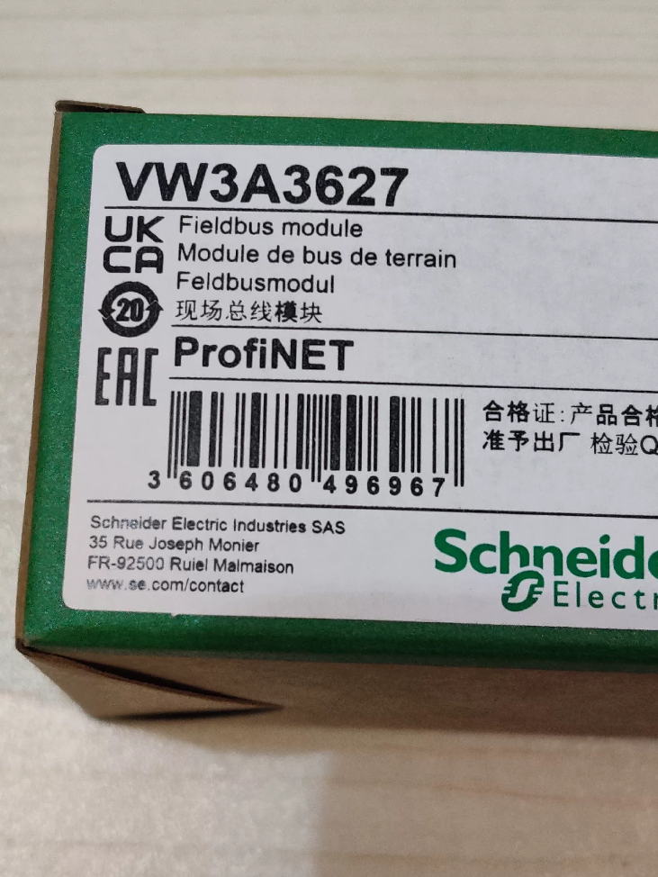

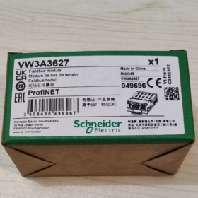
This dedicated PROFINET IO industrial Ethernet communication option card for Altivar variable speed drives integrates a dual-RJ45 switch with plug-and-play expansion. It connects Schneider drives to Siemens PROFINET bus systems and complies with the standard PROFIdrive drive profile.
- Répartition complète du modèle
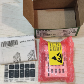
VW3A3627
VW3A: Prefix for Altivar drive communication accessories
36: Ethernet bus module series
27: Dual-RJ45 port PROFINET variant
III. Spécifications techniques de base
| Article | Spécification |
| Protocoles de communication | PROFINET E/S (RT Real-Time / IRT Isochronous Real-Time), LLDP, PROFIdrive V4, embedded HTTP web server |
| Physical Interfaces | 2 × RJ45 (integrated Layer 2 switch; daisy-chain wiring eliminates extra switches) |
| Transmission Rate | 100 Mbps full-duplex |
| Alimentation | Powered by drive backplane; aucune alimentation externe requise |
| Status LEDs | MS Module Status, NS Network Status, Port1 TX/RX, Port2 TX/RX |
| Normes de conformité | CEI 61800-7-201 CiA402, PROFINET Class B/C |
| Classe de protection | IP20 (for cabinet mounting only) |
| Dimensions | 100 × 80 × 20 mm |
| Poids net | 0.3 kilos |
| Fonctions | Web-based monitoring, parameter read/write, fault recording, configuration upload/download, Ethernet statistics & diagnostics |
- Compatible Drive Models (Full List)
- ATV32 / VTT320 (Compact low-power Altivar series)
- VTT340 (Machinery-specific; Sercos variants excluded)
- VTT630 / VTT650 (ATV600 Process series)
- VTT930 / VTT950 (High-power heavy-duty ATV900 series)
- Altivar Process Modular modular variable speed drives
> Incompatible Units: VTT12 / ATV21 / ATV212, legacy VW3A34xx bus card series
- Avantages clés
- Dual-port daisy-chaining: Direct cable interconnection between drives reduces switch ports and simplifies cabinet wiring.
- Embedded Web Server: Drives can be commissioned via browser by plugging a PC directly into the RJ45 port; no dedicated software needed.
- Standard PROFIdrive compliance: Seamless compatibility with Siemens PROFINET PLCs including S7-1200/1500/300/400 and ET200SP.
- Hot-swap capable: The module can be removed and replaced while the drive is stopped without damaging the unit.
- Comprehensive diagnostics: Four LED indicators enable fast troubleshooting of module faults, cable breaks, and missing master station issues.
- Communication Card Series Comparison (Référence de sélection)
| Modèle | Bus Type | Ports | Application typique |
| VW3A3607 | Profibus-DP | Terminal block | Retrofit legacy DP bus systems |
| VW3A3616 | Modbus-TCP / EtherNet/IP | Double RJ45 | Rockwell & domestic brand PLC Ethernet networking |
| VW3A3601 | EtherCAT | Double RJ45 | High-speed motion control |
| VW3A3627 | PROFINET | Double RJ45 | Projects with full range of Siemens PLCs |
| VW3A3608 | CANopen | Double RJ45 | CAN bus for small machinery |
VII. Scénarios d'application typiques
Automotive production lines, conveyor systems, machines d'emballage (paired with Siemens PLCs)
High-power variable frequency control cabinets for chemical processing, water treatment and HVAC (VTT630 / VTT930)
Machine tools and compact automated equipment (VTT320 / VTT340)
Multi-drive daisy-chain networking to cut industrial switch costs
VIII. Troubleshooting Key Points
- Steady red MS LED: Hardware fault, loose module insertion, mismatched drive firmware version
- Steady red NS LED: No PROFINET device name assigned, IP address conflict, broken bus cable
- Unlit port LNK indicator: Damaged Ethernet cable, poor crimp on RJ45 connector, powered-off remote device
- Frequent communication packet loss: Non-shielded Ethernet cable, poor cabinet grounding, routing alongside power cables
- Notes de remplacement
No upgraded alternative within the same platform; VW3A3627 is the only original factory card for PROFINET applications.
No single-port PROFINET original card available; this dual-port model must be used if PROFINET connectivity is required.
Supported Drive Brands for Schneider VW3A3627
- Sole Supported Brand: Schneider Électrique
The VW3A3627 is an original factory plug-in communication card exclusively designed for Schneider Altivar drives. Its hardware slot, underlying driver and power supply protocol are custom-made for Schneider drives. It is completely incompatible with all other brands including Siemens, ABB, Danfoss, Inovance and Delta, with no physical fit or matching communication firmware support.
- Full Compatible Schneider Altivar Drive Series
- Compact Machinery Range: ATV32 / VTT320
ATV32 (legacy low-power): Direct plug-in installation
ATV320-B variants: Equipped with native communication slot for direct insertion
ATV320-C variants: Require additional VW3A3600 adapter to mount this card
- High-End Machinery-Specific ATV340
Compatible models: ATV340U07N4 ~ D22N4, ATV340D30N4E ~ D75N4E
Incompatible models: ATV340U07N4E ~ D22N4E (no expansion slot)
Exclusion: ATV340 Sercos dedicated versions do not support this card
- General High-Power Process ATV600 Series
VTT630, VTT650, Altivar Process Modular modular drives
- Heavy-Duty High-Power ATV900 Series
VTT930, VTT950
III. Clearly Incompatible Legacy Schneider Drives
VTT12, ATV21, ATV212, ATV31, ATV312 (no VW3A36xx expansion slots; only legacy VW3A34xx DP cards are supported)
- Critical Supplementary Notes
- No cross-brand compatibility
Even if drives from other brands support the PROFINET protocol, differing hardware slots and backplane communication buses prevent installation of the VW3A3627, with no matching firmware drivers. Each brand supplies proprietary PROFINET cards: Siemens SINAMICS uses CBE20, ABB ACS uses FPNO-01, Danfoss VLT uses MCA120.
- No brand restriction on PLC side
From a communication perspective, this card interfaces with all PROFINET IO-capable PLCs including Siemens, Innovation, Xinje and Rockwell. The only mounting host must be the aforementioned Schneider drives.
- Installation prerequisite: Matching drive firmware version. Versions below the minimum requirement trigger a red MS hardware fault LED.
Complete Installation Guide for Schneider VW3A3627 PROFINET Communication Module
- Mandatory Safety Pre-Installation Rules (Risk of Electric Shock / ESD Damage)
- Full power cut-off & capacitor discharge
Disconnect main drive power and 24V control power, apply lockout-tagout procedure. Attendez 15 minutes to discharge DC bus capacitors; verify bus voltage is below 42 V with a multimeter before proceeding.
- ESD anti-static protection
Wear an anti-static wrist strap or touch grounded cabinet metalwork to release static charge. Do not touch circuit board gold finger contacts with bare hands—static electricity can permanently damage the module.
- Exigences environnementales
Cabinet free of dust and condensation; température ambiante 0 ~ 50 °C. Keep clear of high-interference sources such as power cables and contactors.
- Parts Checklist
Module: VW3A3627
Mandatory accessory for compact ATV320-C units: VW3A3600 communication adapter
Cabling: Industrial shielded CAT5e / CAT6 Ethernet cable (PROFINET standard)
- Hardware Installation Steps by Drive Model
Modèle 1: ATV320-B (Book-style, no adapter required)
- Remove the dust cover from the front communication slot of the drive.
- Align the module gold fingers with the slot and insert horizontally. Do not push fully home; the alignment mark confirms correct positioning.
- Listen for the click of the locking clip to confirm the module is secured without play.
- Removal: Press the PUSH clip below the module and pull steadily outwards.
Modèle 2: ATV320-C / ATV320-W (Compact / High-protection, adapter required)
- Mount and lock the VW3A3600 adapter onto the side expansion port of the drive first.
- Insert the VW3A3627 horizontally into the adapter slot; the clip locks automatically.
- Removal: Press down the adapter PUSH clip and extract the communication card.
Modèle 3: VTT340 / ATV630/650 / VTT930/950 (Processus / Heavy-Duty High-Power)
- Open the cover of the front expansion slot on the drive.
- Align the module gold fingers with the backplane bus slot and push fully home.
- Press the top module clip to lock securely with no wobble.
- Removal: Pinch both side clips to release and pull the module straight out vertically.
III. Ethernet Cable Wiring Specifications (Dual-RJ45 Daisy-Chain Topology)
- Port definition: Port1 (uplink to PLC / switch), Port2 (downlink to next drive); integrated Layer 2 switch onboard.
- Cabling: Fully shielded industrial Ethernet cable. 360° crimp the cable shield to the metal shell of both RJ45 connectors, with single-point cabinet grounding.
- Wiring routing: Separate Ethernet cables from power cables with a minimum clearance of 30 cm; cross cables perpendicularly where crossing is unavoidable.
- Prohibited practices: Unshielded civilian Ethernet cables, ungrounded long cables, routing cables adjacent to contactors or drive output power cables.
- Pre-Power-On Inspection Checklist
- Module clips fully engaged with no loose or partially inserted state.
- Gold finger contacts free of bending, oxidation or foreign debris.
- RJ45 cable connectors fully crimped, aligned with LNK indicator lights.
- All drive covers reinstalled for complete protection.
- Reliable PE cabinet grounding with ground resistance ≤ 4 Oh.
- Power-On Module Detection & Configuration de base
- Observe module LEDs after power-up:
MS LED: Module status (Green = Normal; Red = Hardware fault / Undetected)
NS LED: Network status (Green = Online; Red = No master station / IP conflict)
Port1/Port2 LNK: Steady on when cable connected; flashing ACT indicates data exchange
- Activate communication card via drive parameters:
Navigate to parameter `COM.` → Select communication type as `PROFINET`
Import the corresponding GSD file into the PROFINET master PLC
Assign device name and IP address, complete hardware configuration
- Installation Prohibitions (Strictly Forbidden Operations)
- Hot plugging/unplugging the module (risks burning the backplane bus, module and drive main control board)
- Touching circuit boards without anti-static protection
- Forcing card insertion into ATV320-C units without installing the VW3A3600 adapter
- Rough force or angled insertion bending gold finger contacts
- Using unshielded Ethernet cables or leaving cable shields ungrounded
- Leaving drive covers removed after module installation (dust ingress may cause short circuits)
VII. Quick Troubleshooting for Common Installation Faults
| Symptôme de panne | Cause première | Résolution |
| Steady red MS LED | Loose module insertion / Outdated drive firmware / Dirty gold fingers | Power off, reinsert module; upgrade drive firmware; clean gold finger contacts |
| Steady red NS LED | Unassigned PROFINET device name / IP conflict / Broken cable | Download device name via PLC configuration; inspect cables; unify IP subnet range |
| Unlit port LNK indicator | Poor RJ45 crimp / Damaged cable / Powered-off remote device | Replace industrial Ethernet cable; re-crimp RJ45 connectors |
| Frequent communication packet loss | Câble non blindé / Mauvaise mise à la terre / Routing near power cables | Fit shielded Ethernet cable; implement solid cabinet grounding; separate wiring routes |


 Relais de sécurité à montage sur circuit imprimé à courant élevé SIR4 Power")
 (IE5099 est le numéro de pièce de commande; IEC3002-BPOG signifie le modèle de spécification de série)")


")
NH42-63-318x560.png "Commutateurs de transfert automatiques de type PC CHINT (ATS)NH42-63/4SZ")


