 Contacteur,disjoncteur,capteur,Encodeur,API,Convertisseur

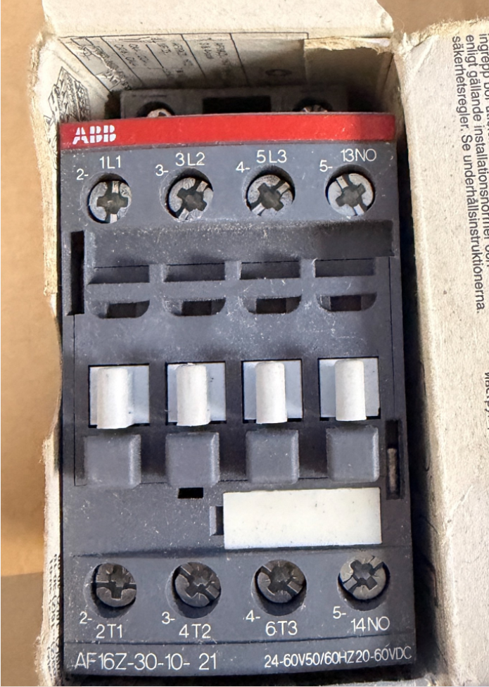

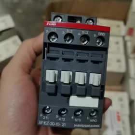
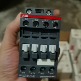
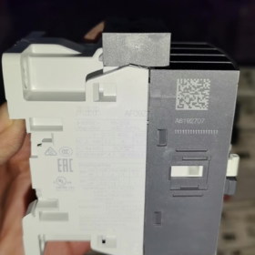
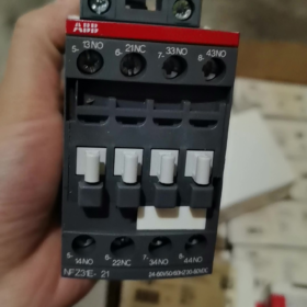
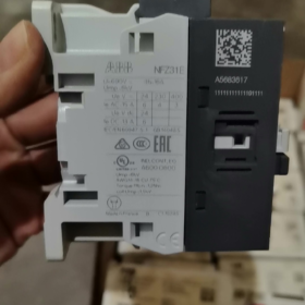
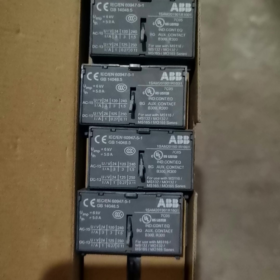
Numéro de commande d'usine d'origine.: 1SBL176001R2110
- Définition de la répartition du modèle
AF16Z 30 10 21
- AF16Z: Série AF; Z = Bobine électronique à large plage de faible consommation (capable d'entraînement direct par API); Taille du cadre 16 classe
- 30: Contacts principaux: 3 Normalement ouvert (3NON), pas de contacts principaux normalement fermés
- 10: Contacts auxiliaires intégrés: 1 Normalement ouvert (1NON), 0 Normalement fermé
- 21: Code bobine → Tension de commande: 24~60 V CA 50/60 Hz / 20~60 V CC
⚠️ Différence entre AF...Z et AF standard: Consommation électrique extrêmement faible de la bobine, prend en charge la conduite directe par les sorties PLC DC24V, résistant aux chutes de tension (conforme à SEMI F47).
- Caractéristiques électriques de base
Tension maximale du circuit principal: 690 V et
AC-1 (charge résistive), ≤40°C ambiante: 30 UN
AC-3 (3-moteur phase, 400 V): 18 UN, adapté pour 7.5 Moteur kW
AC-3 (690 V): 10.5 UN, maximum. 9 kW
Montage: Montage sur rail DIN, connexion par borne à vis
Dimensions hors tout: W 45 mm × H 86 mm × D 77 mm
Température de fonctionnement: -40~+70 °C (sans relais de surcharge thermique); -25~+60 °C (avec relais de surcharge thermique)
- Caractéristiques clés de la bobine
Large gamme AC/DC universelle: C.A. 24 ~ 60 V / C.C 20 ~ 60 V
Suppression de surtension intégrée; aucun amortisseur RC externe ou diode requis
Faible consommation d'énergie de maintien, idéal pour un fonctionnement sous tension continu
Résiste aux fluctuations de tension à court terme et aux chutes de tension
- Identification des terminaux
Circuit principal: 1L1-2T1, 3L2-4T2, 5L3-6T3
Contact auxiliaire: 14NON (Normalement ouvert)
- Alternatives courantes & Distinctions
- AF16Z-30-10-11: Même plage de tension, équipé d'une bobine AF standard (Bobine Z non basse consommation); ne peut pas être directement piloté par des sorties API à faible courant, non interchangeable.
- AX16-30-10: Série économique AX, sans bobine électronique à large portée, tension de commande fixe; ne peut pas remplacer AF16Z.
- Pour 1NO + 1Contacts auxiliaires NF: Sélectionnez le modèle AF16Z-30-11-21.
- Applications typiques
En amont des variateurs de fréquence, les fans & pompes à eau, Équipement CVC, machines à semi-conducteurs, Contrôle de charge direct de sortie PLC DC, sites industriels nécessitant une grande tolérance aux fluctuations de tension.
ABB AF16Z-30-10-21 Contacteur Document technique d'installation
Numéro de commande: 1SBL176001R2110
- Consignes générales de sécurité
⚠️ Toutes les installations, les travaux de câblage et de maintenance doivent être effectués avec toute l'alimentation débranchée; la procédure de consignation-consignation est obligatoire. Les travaux doivent être effectués uniquement par des électriciens qualifiés.
- Classe de protection: IP20. Pour installation en armoire uniquement. Ne pas installer à l'air libre, environnements humides, endroits très exposés à la poussière ou aux gaz corrosifs.
- Normes applicables: CEI/EN 60947-1, CEI/EN 60947-4-1; Certifié UL/CSA.
- L'AF16Z est équipé d'une bobine électronique à large plage de faible consommation avec circuit de suppression de surtension intégré. Aucun amortisseur RC externe ou connexion de diode n'est requis.
- Informations de base sur le produit
2.1 Définition du modèle
AF16Z: Série AF, taille du cadre 16, Z = bobine électronique basse consommation
30: 3 contacts principaux normalement ouverts
10: Intégré 1 contact auxiliaire normalement ouvert
21: Plage de tension de bobine AC 24 ~ 60 V 50/60 Hz / C.C 20 ~ 60 V
2.2 Dimensions hors tout
Largeur 45 mm × hauteur 86 mm × Profondeur 77 mm
2.3 Tableau récapitulatif des notations
| Article | Paramètre |
| Charge résistive AC-1 (40 C) | 30 UN |
| Charge du moteur AC-3 (400 V) | 18 UN, compatible avec 7.5 Moteur triphasé kW |
| Tension de fonctionnement maximale | 690 V et |
| Température de fonctionnement (sans relais thermique) | -40 C~ +70 C |
| Température de fonctionnement (avec relais de surcharge thermique) | -25 C~ +60 C |
- Spécifications d'installation mécanique
3.1 Méthodes de montage
Deux options de montage disponibles:
- Montage sur rail DIN (Recommandé)
Norme ferroviaire: TS35 (35×7,5 mm / 35×15 mm)
Opération: Accrochez le loquet inférieur au rail, appuyer jusqu'à ce qu'un clic audible confirme le verrouillage. Pour le retrait, utilisez un tournevis plat pour soulever le loquet inférieur et soulevez-le vers le haut.
- Montage par vis sur la plaque de base
Fixez en diagonale à l'aide 2 × Vis M4; reportez-vous au dessin d'encombrement pour l'espacement des trous de montage.
3.2 Orientation de montage & Autorisation
- Montage vertical (bornes en haut & bas) préféré. 90° le montage latéral horizontal est autorisé; l'installation à l'envers est interdite.
- Plusieurs unités peuvent être montées côte à côte sans déclassement de courant. Maintenir un dégagement vertical ≥15 mm pour la ventilation; tenir à l'écart des composants générateurs de chaleur tels que les résistances et les onduleurs.
- Évitez l’installation dans des endroits à fortes vibrations. Accélération des vibrations >0.5g nécessite des mesures d'amortissement des vibrations.
- Spécifications du câblage électrique
4.1 Définition du marquage des bornes
Circuit principal supérieur: L1, L2, L3 (Entrée d'alimentation)
Circuit principal inférieur: T1, T2, T3 (Sortie de charge)
Les applications non UL permettent une alimentation par le haut ou par le bas; Les installations certifiées UL nécessitent une entrée d'alimentation à partir des bornes L supérieures.
Bornes de bobine A1, A2: Entrée du signal de commande (AC/DC non polarisé)
Contact auxiliaire 13-14: Contact normalement ouvert intégré (1NON)
4.2 Spécification du câble & Longueur de dénudage
Longueur de dénudage standard: 10 mm
Conducteurs du circuit principal: Câble en cuivre massif/brin 1~6 mm²; embouts recommandés pour les câbles flexibles
Contrôle / conducteurs du circuit auxiliaire: 0.75~2,5 mm²
4.3 Couple de serrage (Obligatoire)
Bornes du circuit principal: 1.5 N·m
Bobine A1/A2 & bornes de contacts auxiliaires: 1.2 N·m
Un couple insuffisant provoque une surchauffe des bornes; un couple excessif entraîne un dénudage du filetage.
Outils recommandés: Tournevis Pozidriv PZ2 / 5.5 Tournevis dynamométrique plat mm.
- Notes d'application critiques des bobines (Fonctionnalité principale de l'AF16Z)
- Plage de tension: AC24 ~ 60 V / DC20 ~ 60 V, compatibilité de tension étendue, entraînement direct par sorties DC PLC.
- Très faible consommation électrique de maintien de la bobine, adapté à un fonctionnement sous tension à long terme; conforme aux exigences d'immunité contre les chutes de tension SEMI F47.
- A1 et A2 sont non polarisés; la polarité n'a pas d'importance pour le contrôle DC24V.
- N'appliquez pas de tension de commande dépassant 60 V, sinon le module de bobine électronique sera détruit.
- Installation d'accessoires en option
- Contacts auxiliaires latéraux (série CA4)
S'enclenche sur les fentes latérales gauche/droite sans outils. Maximum 2 des jeux de contacts auxiliaires latéraux peuvent être montés sur AF16.
- Verrouillage mécanique
Installer pour la configuration du circuit d'inversion de deux contacteurs AF16Z pour éviter la fermeture simultanée et les courts-circuits entre les phases avant et arrière.
- Correspondance du relais de surcharge thermique
Compatible avec les relais thermiques de la série TA25DU, montage direct par encliquetage sous le contacteur.
- Procédure de mise en service après la mise sous tension
- En condition de mise hors tension: Inspection visuelle pour un câblage correct, pas de débris métalliques, toutes les bornes sont serrées au couple spécifié.
- Actionner manuellement le mécanisme du contacteur pour confirmer le bon fonctionnement sans blocage.
- Tester le circuit de contrôle indépendamment: Appliquer la tension de commande nominale à A1/A2; le contacteur doit s'enclencher de manière fiable et se retirer en douceur lors de la coupure de courant.
- Vérifier la commutation synchrone du contact auxiliaire 13-14 avec fonctionnement par contacteur.
- Connectez le circuit principal pour un test à vide; vérifier s'il y a un bruit anormal et une augmentation rapide de la température des bornes.
- 30-test de fonctionnement en charge minute; revérifiez la température du terminal pour vous assurer que l'augmentation de la température reste dans les limites autorisées.
- Défauts d'installation & Pratiques interdites
❌ Opérations interdites:
Brins libres exposés sur les bornes de câble
Serrage des bornes sous tension
Tension de commande en dehors de la plage 20~60 V
Blocage des canaux de ventilation au-dessus et en dessous du contacteur
Installation directe dans des environnements avec poussière combustible ou condensation continue
Problèmes courants après l'installation
- Claquement du contacteur/enclenchement instable: Vérifiez que la tension de commande est supérieure au niveau de fonctionnement minimum; vérifier la chute de tension le long des câbles de commande.
- Surchauffe des bornes: Resserrez les bornes au couple spécifié; confirmer que la section transversale du conducteur est adéquate.
- Échec de l'arrêt lorsqu'il est piloté par le PLC: Confirmez que l'unité est AF16Z (bobine de faible puissance); la bobine AF16 standard ne peut pas être directement pilotée par les sorties transistor PLC.
- Exigences d'entretien
- Inspection périodique de la température des bornes et du bruit anormal.
- Évitez les commutations répétées au-dessus du pouvoir de coupure nominal.
- Ne faites jamais fonctionner le contacteur avec le bouclier anti-arc retiré.. Remplacez l'unité complète lorsque les contacts subissent une ablation grave.
Paramètres de durée de vie mécanique d'ABB AF16Z-30-10-21
L'AF16Z partage une construction mécanique identique avec l'AF16 standard. Données techniques officielles:
✅ Endurance mécanique: 10 millions de cycles de manœuvres (10×10⁶ opérations)
Conditions d'essai: Tension de commande nominale, commutation à vide, température ambiante standard.
Paramètres clés pris en charge
- Fréquence de fonctionnement mécanique maximale: 3,600 opérations par heure
Le fonctionnement continu à haute fréquence ne doit pas dépasser cette limite pour éviter une usure mécanique accélérée.
- Endurance électrique de référence (dépend du type de charge, pas égal à la durée de vie mécanique)
AC-3 (400 Charge du moteur V): Environ. 1,000,000 cycles
AC-1 (charge résistive): Environ. 1,600,000 cycles
⚠️ L'endurance mécanique représente la limite mécanique de fonctionnement; la durée de vie dans les applications pratiques est normalement déterminée par l'érosion électrique des contacts.
Remarques supplémentaires
- L'AF16Z ne diffère que par sa variante de bobine électronique à large plage de faible consommation. Armature, la structure mécanique de la tringlerie et des contacts est identique à la norme AF16; les indices d’endurance mécanique restent inchangés.
- L'endurance mécanique réelle diminuera dans des environnements difficiles (forte poussière, vibration continue, haute température).
- Définition de l'endurance mécanique: Cycles de manœuvres d'enclenchement/décrochage du contacteur pilotés par bobine uniquement, sans charge connectée au circuit principal.










NH42-63-318x560.png "Commutateurs de transfert automatiques de type PC CHINT (ATS)NH42-63/4SZ")



